- Contact Us
- +91-98111-55335
- [email protected]

“Data Quality Is A Top Barrier To Successful Adoption Of AI”
September 11, 2020
Software and Mobile Apps For Renewable Energy
September 18, 2020DIY: Hand Gesture Based Wireless AC Light Dimmer
 This project is based on MPU6050 accelerometer sensor and Arduino to wirelessly control the brightness of light. MPU6050 accelerometer senses the tilt positions of your hand in the X-axis and Y-axis and provides digital readings. Arduino Nano reads this data and transmits it using a 433MHz RF module. This data is received at the receiver end and used to control the brightness of light as per the movement of your hand.
You can use this circuit to control the brightness of light as well as the speed of a fan. The circuit is especially useful for a differently-abled person.
Circuit and working
The circuit of hand gesture-based wireless AC light dimmer comprises a transmitter and a receiver.
Transmitter. The circuit diagram of the transmitter is shown in Fig. 1. It has the Arduino Nano board (Board1), 433MHz RF transmitter module (TX1), 9V battery, and MPU6050 accelerometer sensor.
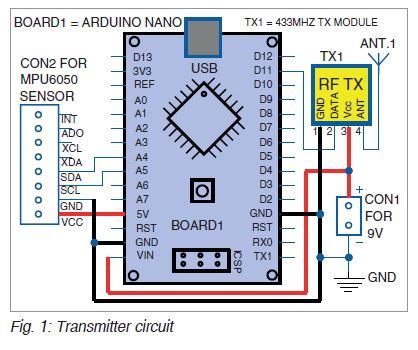
The transmitter module (TX1) has four pins, namely, Vcc, data, ground (GND), and antenna (ANT), as shown in Fig. 1. The Vcc pin can have a wide range of input voltage from 3V to 12V. The transmitter consumes a minimum of 9mA current, which can go as high as 40mA during transmission.
The data to be transmitted is fed to data pin. This signal is then modulated using ASK (amplitude shift keying) and sent through the air at a frequency of 433MHz. The speed at which it transmits data is around 10kbps.
MPU6050 sensor has an integrated 3-axis MEMS (micro electrical mechanical system) accelerometer and 3-axis MEMS gyroscope. MPU6050 is a 6 DOF (degree of freedom) or 6-axis IMU (inertial measurement unit) sensor. It gives six values in the output—three values from the accelerometer and another three from the gyroscope. This sensor uses the I2C protocol for communication. The accelerometer works on the principle of the piezoelectric effect.
Arduino Nano has thirty pins. Its VIN pin is connected to the positive terminal of the 9V battery. GND pin is connected to the negative terminal of the battery.
MPU6050 is an 8-pin sensor. Its VCC pin is connected to 5V of Arduino Nano. GND pin is connected to the GND pin of Arduino. Pins SCL and SDA of the sensor are connected to pins A5 and A4 of Arduino, respectively. Pin 1 of the TX1 module is connected to GND, pin 2 to pin D11 of Arduino Nano and pin 3 to +9V. Pin 4 (ANT) is connected to an antenna for long-distance transmission.
Software. Arduino IDE is used for programming the Arduino Nano. Connect Arduino to PC/laptop using a USB cable. Open the source code/sketch (xyz_tx.ino). Do not forget to include the related libraries such as Adafruit MPU6050, string library, and virtual wire library. Compile the source code. Select the COM port and board from Tools menu in Arduino IDE. Now, upload the source code xyz_tx.ino to Board1.
You can test the code by opening Serial Monitor in Arduino IDE. If your connections are proper and correct, it will show ‘Successfully Connected’ message. You can see X-axis and Y-axis data on your Serial Monitor. If nothing is displayed on Serial Monitor, refer xyz_tx.ino source code at line number 14 at //Serial.begin(9600). Remove double slash, compile, upload, and then check the data again on Serial Monitor.
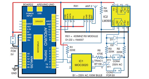
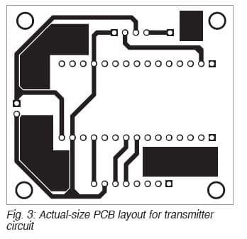
Receiver. The circuit diagram of the receiver is shown in Fig. 2. It has an Arduino Uno (Board2), 433MHz RF receiver module (RX1), MOC3020 optocoupler (IC1), BT139 (TRIAC1), LM393 op-amp (IC2), 230V AC, 100-watt bulb (B1) and some basic electronic components.
Triac is a three-terminal semiconductor device. It is bi-directional and can switch high voltage and current of AC signals. This device is widely used in AC power control applications.
The RF receiver module (RX1) receives the modulated RF signal and then demodulates it. It consists of eight pins. Its VCC and GND pins are connected to 5V and GND pins of the Arduino, respectively. The data pin is connected to pin 12 of the Arduino Uno.
LM393 op-amp is used for zero-crossing detection of AC signals. Resistor R4 is used as a pull-up resistor, while resistors R2 and R3 are used to drop AC voltage. Diodes D1 and D2 are used to protect the op-amp from damage due to an increase in input voltage. Square wave signal is obtained at pin 1 of IC2.
In the triac firing circuit, connect pin 1 of IC1 to 5V through resistor R1 and pin 2 to pin 3 of Arduino. Resistor R5 is connected between IC1 and MT2 terminal of the triac. The control signal output is available across MT1 and MT2 terminals of the triac.
When a 5V power supply is connected to Arduino, it starts receiving transmitted data through the RX1 module. This received data is used to control the triac using PWM signals. The output voltage across the triac can be used to control electrical appliances such as a bulb (B1) or fan. For instance, it can be used to control the speed of the fan or brightness of the bulb. You can check the received output signals on the Serial Monitor.
Software. Before connecting the receiver circuit to Arduino Uno, you need to upload the xyz_rx.ino code to the Arduino Uno board (Board2). Arduino IDE is used for programming Arduino Uno. Open the source code/sketch, compile it, and select COM port and board from Tools menu in Arduino IDE. Upload the source code to the Arduino Uno board.
Construction and testing
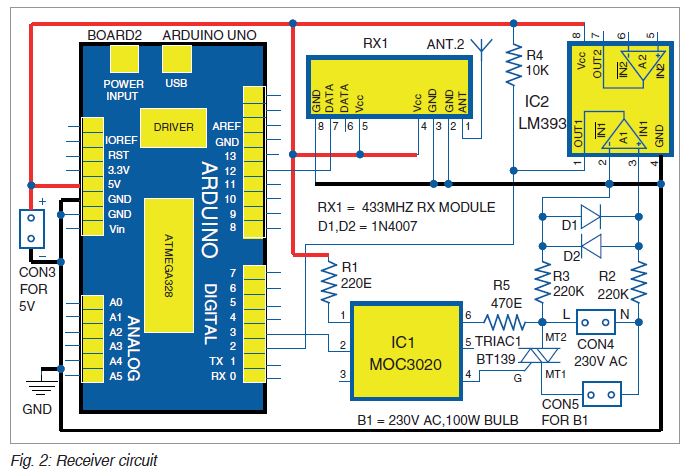
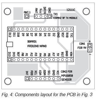
An actual-size PCB layout for the transmitter is shown in Fig. 3 and its components layout in Fig. 4. After assembling the circuit on the PCB and uploading the source code xyz.tx.ino into Arduino Nano, connect 9V DC at CON1. Your transmitter is now ready to use.
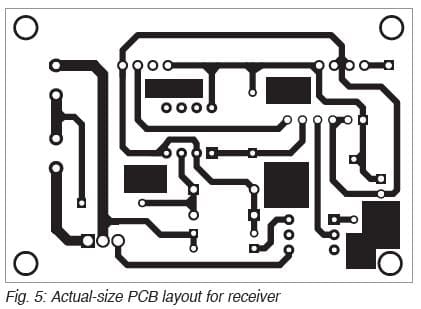
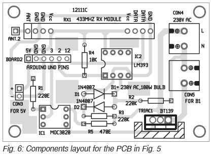
An actual-size PCB layout for the receiver circuit is shown in Fig. 5 and its components layout in Fig. 6. Before using Arduino Uno, do not forget to upload xyz_rx.ino. After assembling the circuit on the PCB, connect 5V DC at CON3. Connect 230V AC, 50Hz mains across CON4, and connect 230V AC, 100-watt bulb across CON5. Now your receiver circuit is ready to use.
Keep some distance between transmitter and receiver units. Hold the transmitter unit in your hand and tilt the unit up and down. The intensity of the light bulb will increase or decrease depending on the position and the tilt angle of the MUP6050 sensor in the transmitter unit.
—Ajay Saini is a senior engineer at Infinity Micro Solutions, Ludhiana