- Contact Us
- +91-98111-55335
- [email protected]

Industrial Robotics Standards For Safety And Efficiency
September 5, 2020
Six-Junction Solar Cells Can Reach Astounding Efficiency Of 47 Per Cent
September 11, 2020DIY: Solar Day Lamp With Battery Backup
 This solar day lamp with battery backup can be used in offices, homes, shops, warehouses, temples, etc. It offers a cost-effective way of harnessing solar energy. It is simple to manufacture and has a long life.
The basic solar day lamp (SDL) consists of only two parts: photovoltaic (PV) panels and LED arrays. Due to simple construction, the SDL offers most cost-effective way of harnessing solar energy (off grid). SDL is ideally suited for offices working from 9am to 5pm. It provides light throughout the day.
However, this simple design has some drawbacks. It leads to energy wastage during weekends when the office is closed. Also, energy is wasted from sunrise till the time the office opens.
In order to improve the energy utilisation of SDL, a partial battery backup system is proposed here. The backup stores part of the energy that otherwise goes unutilised. There is a tradeoff between the amount of energy to be backed up and the overall cost of the system. A partial backup offers improved utilisation of SDL while keeping the system’s cost low. (However, this proposed design cannot be used to charge the battery through AC mains.)
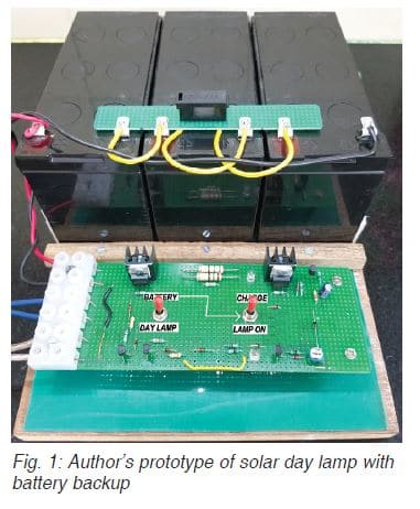
The energy thus stored can be used during low sunlight, cloudy weather, and also in the evenings. The energy stored during weekends can be utilised during weekdays. This circuit can also be used as an emergency lamp. The author’s prototype is shown in Fig. 1.
PV and battery voltage matching
PV panels and batteries follow different voltage standards. A 12V PV panel generates 17.5V at the maximum power point, while a lead-acid battery is designed for 12V nominal voltage. Following a combination of PV panels and batteries provides a good match.
If two 12V PV panels are connected in series, the total PV voltage generated at maximum power point (Vmp)=17.5 ×2=35V.
And with three 12V lead-acid batteries connected in series, the nominal voltage of the battery bank (Vb)=12×3=36V
Thus, we can see that the nominal voltage of a battery bank and the voltage of PV panels match very closely. There will be a slight mismatch in the voltages based on the state of charge of the battery, which is taken care of during circuit design.
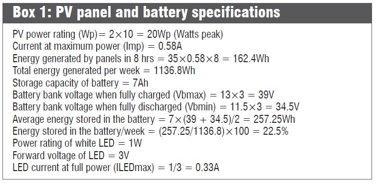
The above combination is given as an example. Users can explore other combinations based on their power needs and investments. Power can be determined from the specifications of PV panels and batteries, as shown in Box 1.
Circuit and working
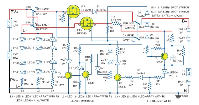
Circuit diagram of the solar day lamp with battery backup is shown in Fig. 2. It is built around two P-channel MOSFET IRF9540 (IRF1 and IRF2), BC556 transistor (T1), three BC546 transistors (T2-T4), two 10W photovoltaic panels (PV1 and PV2), three 12V, 7Ah batteries (BATT.1 through BATT.3), three white LED arrays (LED1 through LED33), 1-kilo-ohm potmeter (VR1), two DPDT switches (S1 and S2), and a few other components.
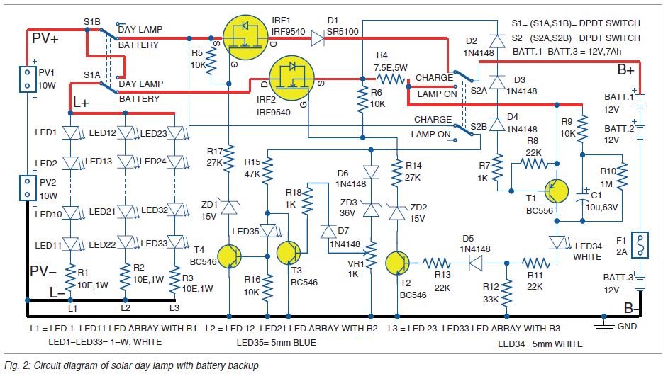
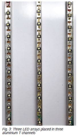
Modes of operations. The lamp consists of three LED arrays (L1, L2, and L3), which are placed in three aluminium T channels (refer Fig. 3). The three LED arrays are connected in parallel with a resistor in each array. Note that the values of resistors R1, R2, R3, and R4 given in this design are just examples. Based on the cable lengths used in the system, these values may have to be slightly tweaked to get optimum performance.
Three lead-acid batteries (BATT.1, BATT.2, and BATT.3) are connected in series. Fuse F1 is connected between BATT.2 and BATT.3. The author’s prototype in Fig.1 shows the battery bank (BATT.1 through BATT.3) mounted on a single base. A small PCB on top of the battery bank is used to mount the fuse.
The proposed circuit operates in the following three different modes:
1. Day lamp mode
2. Battery charging mode
3. Lamp on mode (using battery power)
Two double-pole double-throw (DPDT) switches S1 and S2 are used to change the operating modes of the circuit. IRF1 MOSFET is used to turn off the circuit when batteries are fully charged, and IRF2 MOSFET is used to turn off the circuit when batteries are fully discharged.
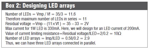
Day lamp mode. In this mode, the PV voltage generated by panels is directly connected to the lamp. This is done by moving switch S1 to ‘day lamp’ position. LED arrays L1, L2, and L3 turn on, and no other part of the circuit gets power supply. The design details of the lamp are shown in Box 2.
Battery charging mode. For charging the battery, S1 is moved to ‘battery’ position and S2 to ‘charge’ position. The glowing of LED35 indicates battery charging mode. In this mode, panel current passes through IRF1, D1, and the battery bank.
In order to ensure IRF1 is on, the circuit comprising D6, ZD3, and VR1 is connected to PV+ through S2B and S1B. If the battery voltage is less than 36.7V, T3 is cut off. Current flowing through resistor R15 and LED35 turns on T4. This pulls down the gate voltage of IRF1 with respect to the source terminal. Hence, IRF1 turns on.
When batteries are fully charged, the voltage across VR1 turns on T3, and IRF1 is turned off. VR1 is used for setting the voltage for charging batteries. The purpose of diode D1 is to stop reverse battery current when PV voltage is not available. The solar panels can generate an open-circuit voltage of about 40V. Hence, it can charge the batteries up to 39V.
Lamp on mode. In this mode, the lamp is turned on using power from the battery bank (BATT.1 through BATT.3) When S2 is moved to ‘lamp on’ position, the battery bank gets connected to the lamp through resistor R4 and IRF2. LED34 glows, indicating that the lamp is on. When the battery voltage goes down, the drop across R4 reduces, causing IRF2 to turn off.
Construction and testing
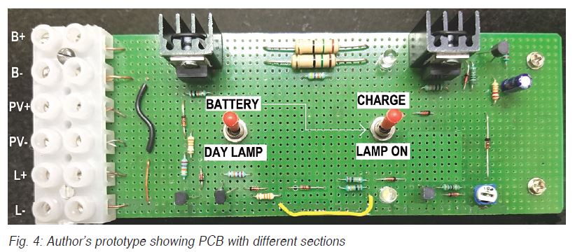
An actual-size PCB layout for the solar day lamp with battery backup is shown in Fig. 5 and its components layout in Fig. 6. After assembling the circuit on PCB, connect PV panels, LED arrays, and batteries.
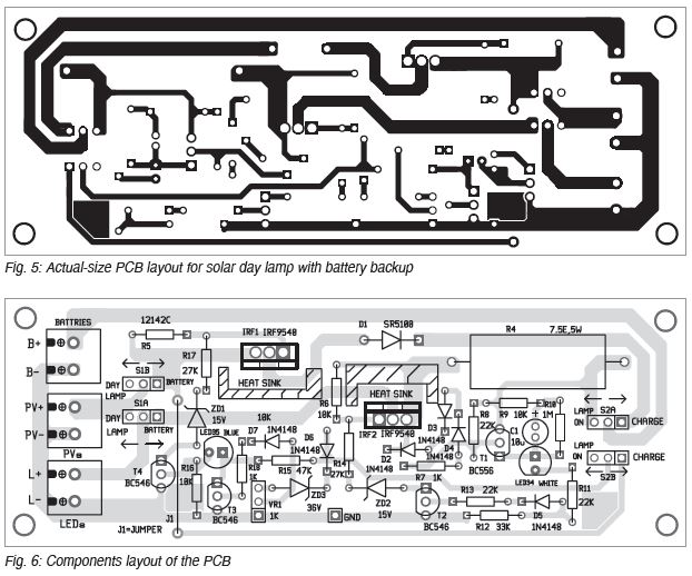
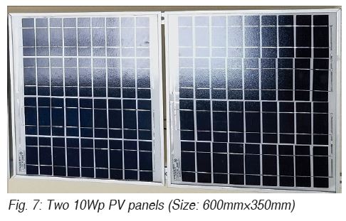
Fig. 7 shows two PV panels mounted on aluminium frames. PV panels should be placed where sunlight is available throughout the day. Usually, the wire/cable from the PV panel to the circuit is long, so a good-quality 1 sq mm cable should be used. But if the wire from PCB to the lamp is short (less than 3 metres), an ordinary wire can be used.
In the evening before leaving office and in weekends, set to battery charging mode.
Note. Instead of using individual 1W LEDs, you can use metal-clad LED PCBs (either round or strip form) that are normally used in LED lamps and tubelights.
—Dr Vijay Deshpande currently works for solar energy projects. He has also worked as electronics hardware engineer in several companies