- Contact Us
- +91-98111-55335
- [email protected]

“Everyone With A Smartphone Now Has A Personal Satellite Navigation System”
June 26, 2020
Solving water crisis with air and nanotechnology
June 26, 2020DIY: OTP Based Wireless Smart Lock System

 This is a one-time password (OTP) based smart locking system using Arduino and Bluetooth. It can generate a new password every time you try to unlock it, which gives you extra security.
A key-based locking system has now become outdated because if your key is lost or stolen, it creates a huge problem. Also, the electronic wireless locking system is not that safe because you might forget your password, or it might get stolen by others while entering the password on your device. So, we can make a DIY smart lock that has the capability to remove all these security threats and problems.
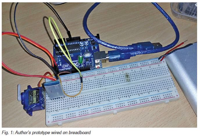
The author’s prototype wired on a breadboard is shown in Fig. 1.
 To start the project, we need the following hardware components/materials:
• Arduino Uno
• Bluetooth HC-05
• Jumper wires
• Servo motor
• LED
• 5V battery or power bank
• USB type-B cable for programming Arduino
• Breadboard or veroboard PCB
After collecting all these components, start the project by writing an Arduino code.
Coding
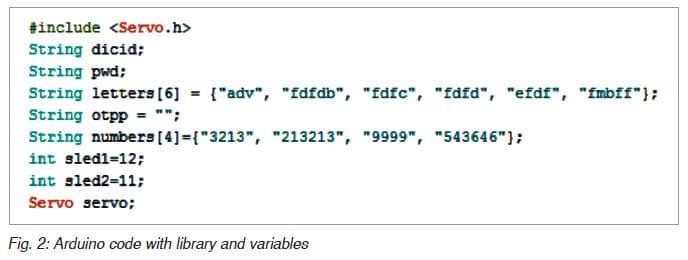
First, we need to include the library and declare variables, as shown in code snippet Fig. 2. Include a servo library and then create a string array to generate a password. Next, create a few more string variables to store the password, OTP, and LED pin numbers as given in code snippet.
Now, in the second code snippet, we need to set up serial and baud rate for Bluetooth as shown in Fig. 3. Set up a pin for servo using servo.attach (PWM pin number) function. Then define pin mode as output for LEDs.
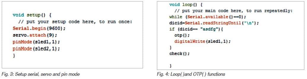
In the third part of the code, create a loop, and check the incoming data from Bluetooth. Next, create ‘if statement’ to check the device ID. If it matches, create OTP ( ) function for generation of OTP as shown in Fig. 4.
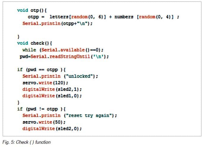
In the last part of the code, as shown in Fig. 5, create a check ( ) function to check whether OTP is correct or not. If it is correct, turn the servo to an open position to unlock the locking system.
Congrats, you have done Arduino coding part!
Now, let’s develop an Android app for our project. We can develop an Android app on two different platforms—Android Studio and MIT App Inventor. Here, let’s choose the MIT App Inventor because it’s easy to make an app with blocks and without normal coding.
Android app development
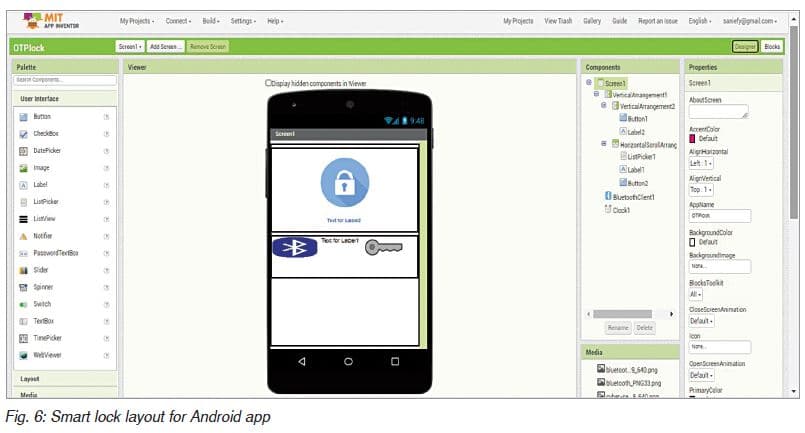
First, you need to have a valid Google email account. Next, open the link https://appinventor.mit.edu to start the MIT App Inventor project. You will find two tabs—Designer and Blocks on the top right side of the screen. Create a layout from the designer section, as shown in Fig. 6. Just drag and drop the components from the user interface (UI) on the left side or download the .aia file from source.efymag.com.
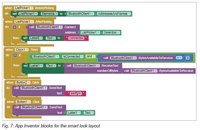
Now, select the Blocks tab to start blocks coding. (In this platform, you can program the app’s behaviour by putting blocks together). First, we need to initialise Bluetooth list available for connection from the App Inventor Blocks Editor section. Then we need to set a button function to send device ID according to our Arduino code, as shown in Fig. 7.
Now, save the file as .apk on your computer. Transfer .apk file to your Android smartphone and install it.
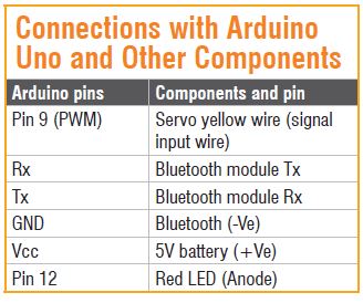
We are almost done now. We have completed Arduino coding and Android app development. Now, let’s start our hardware setup and connections. The circuit connections with the Arduino Uno board and other components are given in the table and also shown in Fig. 8.
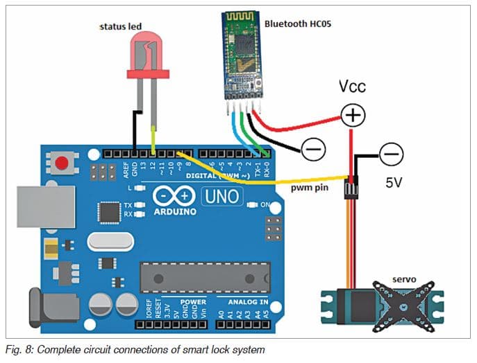
Next, let’s crosscheck everything, including connections. Wrong connections can damage your costly Arduino board. Do not connect servo motor directly to the 5V pin of Arduino. It is not safe because Arduino has not been made for the amount of current that is required for servo motor to operate. Use a separate 5V DC supply for the servo motor. For interfacing the servo motor with the actual lock, you may refer to the ‘Make Your Own Smart Wireless Biometric Lock’ DIY article published in February issue.
Congrats, you have completed your awesome project! Now, switch on your OTP based smart wireless locking system and follow the steps given below:
1. Open the installed OTP_Smartlock app and turn on the Bluetooth in your Android phone.
2. Touch on the Bluetooth icon to get a list of Bluetooth connections for pairing.
3. Select HC-05 from the list. On successful pairing, you will get a ‘connected’ message on the app.
4. Touch on the key icon to send the device ID. If the device ID of app and lock matches, then an OTP will be received in the app next to the key icon.
5. Touch the lock icon and enter OTP in the text bar. If everything is fine, the servo motor will move to unlock the lock. At the same time, the onboard LED of Arduino will light up, indicating successful unlocking of the smart lock
system.
—Ashwini Kumar Sinha is an electronics hobbyist and tech journalist at EFYi