- Contact Us
- +91-98111-55335
- [email protected]

Exploring The Applications Of IoT
May 8, 2020
“Conversational AI Can Help Communications Scale Up Tremendously”
May 8, 2020DIY: Surround Yourself With Sound From Three-Channel Audio Amplifier
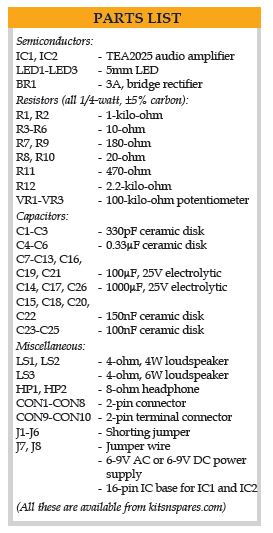
This article presents a simple, low-cost audio amplifier with three channels built around two TEA2025 ICs. The amplifier works from an AC or a DC power supply in the range of 3V to 12V (max. 15V).
This audio amplifier has a left channel, a right channel and one additional channel for the sum of the signals from both channels or for subwoofer or other audio effects.
Description of the circuit
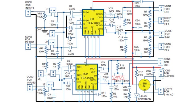
Circuit diagram of the 3-channel audio amplifier is shown in Fig. 1. It is built around two TEA2025 ICs (IC1 and IC2). Each IC has two internal audio amplifiers.
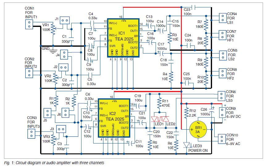
 The input audio signal is applied to connectors CON1, CON2 and CON3. IC1 works as two separate audio amplifiers, each of them with output power more than 2W. The suggested loads across IC1 are loudspeakers LS1 and LS2 (connected to CON4 and CON5) with a power of 4W or more.
Also, you may use appropriate headphones (HF1 and HF2) with an impedance of 8-ohm or more, connected to CON7 and CON8.
IC2 works as a single bridge amplifier with output power more than 4W. It is suggested to use loudspeaker LS3 (connected to CON6) with a power of 6W or more.
A 6-9V DC voltage can be applied to connector CON9 and 6-9V AC voltage to connector CON10. You can use a 50/60Hz 230V AC primary to 9V rms, 3A secondary transformer X1 for AC supply at CON10. A 3A bridge rectifier BR1 is used across CON10. Alternatively, you can use four 1N540X or similar diodes with at least 3A and 50V ratings in place of BR1.
Amplifier voltage gain
TEA2025 has relatively high voltage gain, which can reach 220dB or 47dB. Approximate voltage gains in the TEA2025 amplifier in different modes of operations are listed in Table 1.
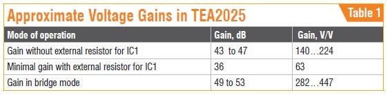
Use external resistors to reduce the gain down to around 36dB. But reducing the gain to less than 36dB will make the amplifier unstable. External resistors can be connected between pins 11 and 6 of IC1 and the corresponding capacitors C7 and C8 to stabilise.
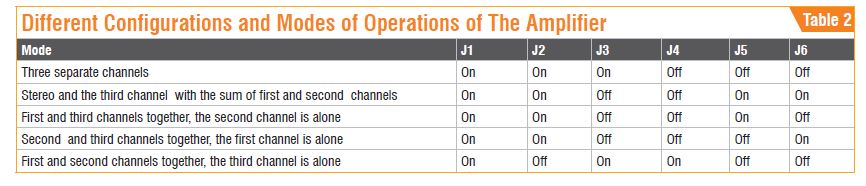
The amplifier has six shorting jumpers J1 through J6 to have different modes of operation. Some of the configurations are given in Table 2.
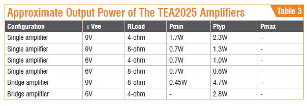
Output power
The output power of the amplifier depends on the power supply and the load resistance (loudspeaker). Table 3 gives information about the approximate output powers (minimum, typical and maximum) of TEA2025 for different configurations and load resistances (Rload). IC1 works as two simple amplifiers and IC2 works as a single bridged amplifier with higher output power.
 The input impedance of the IC TEA2025 is typically 30-kilo-ohm. Here we use three external potentiometers (VR1 through VR3), each of 100-kilo-ohm, to adjust the volume of the corresponding channel inputs.
The circuit has three LEDs. LED1 and LED2 are used as simple level indicators. These produce light proportional to the level of the output signal of the third channel, which is the most powerful channel that works in bridged mode. LED3 is the power on/off indicator.
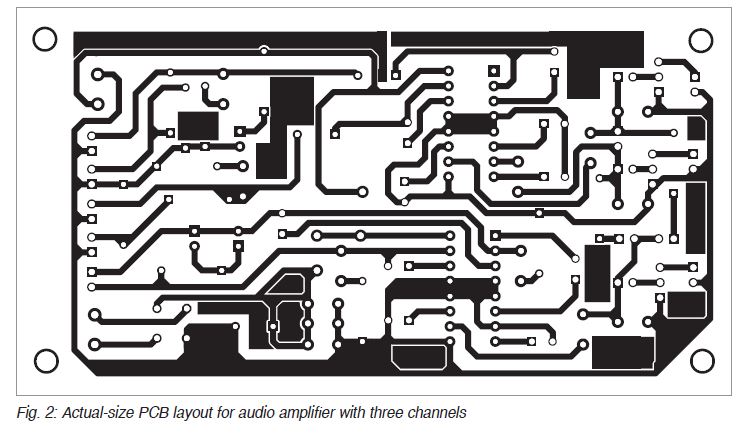
Construction and testing
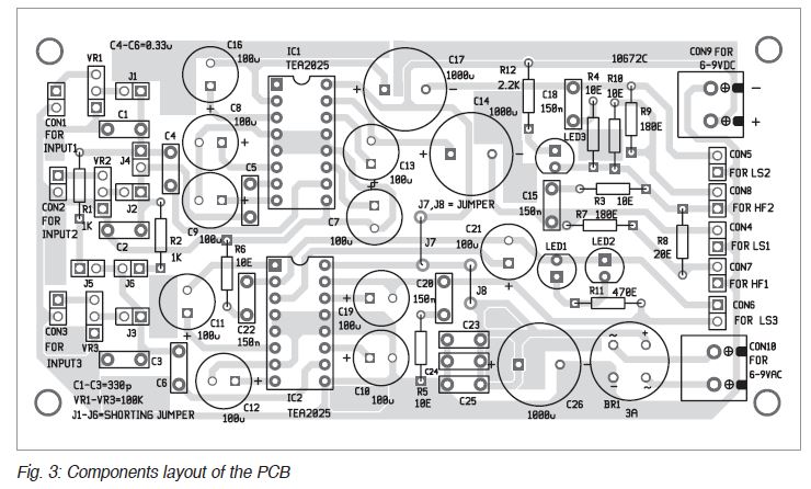
An actual-size PCB layout for the amplifier is shown in Fig. 2 and its components layout in Fig. 3.
The circuit can be tested with DC input voltage (6V-9V) applied to connector CON9 or AC input voltage (6 to 9Vrms) applied to connector CON10. The test input signals (about 10mV rms, depending on the power supply) are applied to CON1, CON2 and CON3.
—Petre Tzv Petrov was a researcher and assistant professor at the technical University of Sofia, Bulgaria, and expert-lecturer in OFPPT (Casablanca), Kingdom of Morocco. Now he is working as an electronics engineer in the private sector in Bulgaria